
Quick lead — why this framework matters
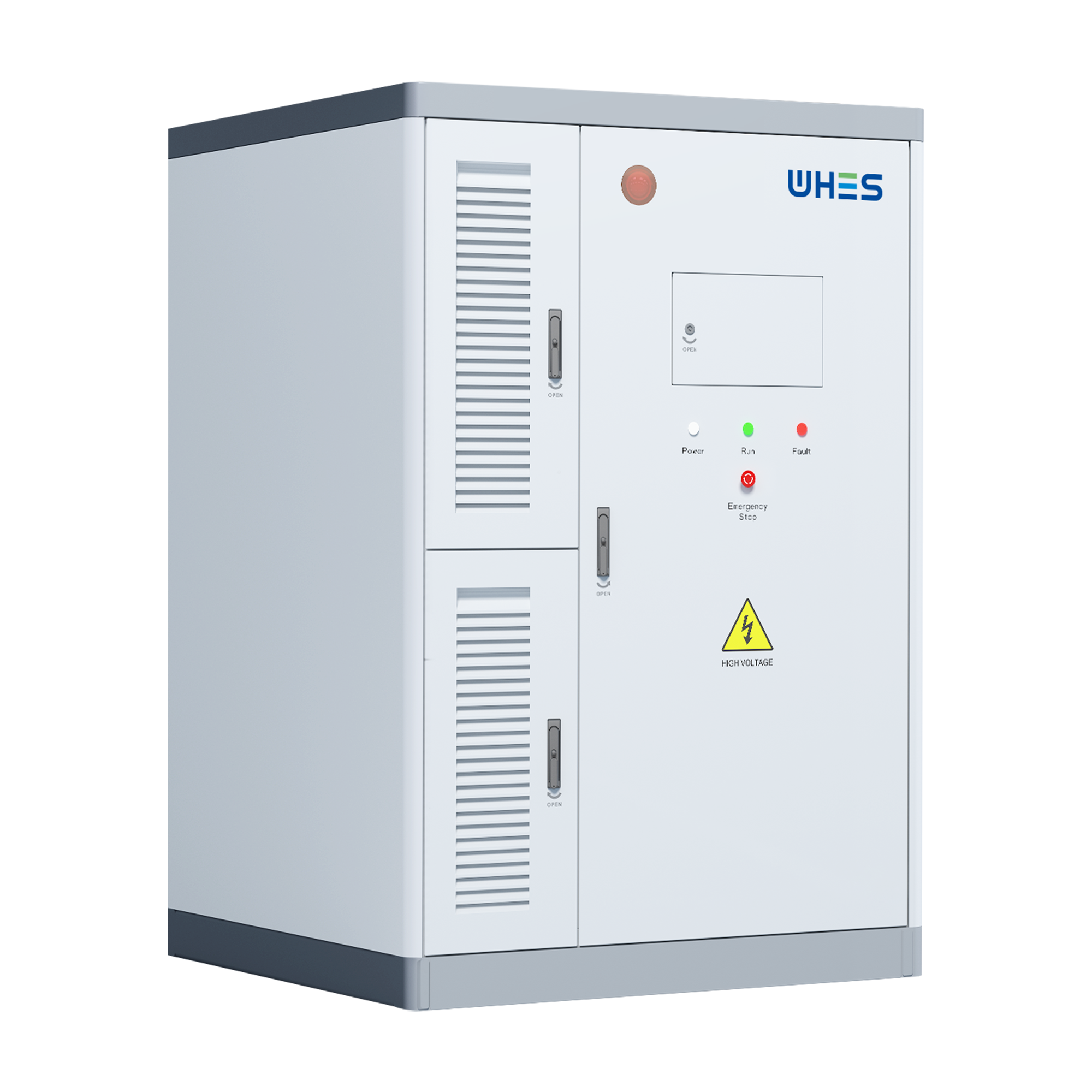
Look, if you’re an engineer or a building boss trying to spec AI-driven energy systems, you want something tight — not vague fluff. This framework walks you through how to balance round-trip efficiency (RTE) and thermal stability in real projects, so your storage actually behaves on the grid and in the plant. I’ll even point you at practical kit like a home battery energy storage system when it fits the spec, because sometimes the best move is picking the right product early.
Framework overview — four pillars to spec a winning system
We use four pillars: performance targets, thermal strategy, control logic, and verification. Together they form a checklist you can hand to procurement or ops and expect real results. Each pillar links back to how an AI controller treats state-of-charge (SoC), RTE, and cell temps — so you’re not just chasing a headline number.
Pillar 1: Set realistic performance targets
Start with clear RTE goals and what they mean for operations. Are you optimizing for daily cycling or long-duration backup? RTE affects how much capacity you schedule for peak shaving versus resiliency. Include DoD and expected cycles per year. Keep targets express: e.g., “87–90% RTE under 25–75% SoC window, 4,000 cycles life.” That kind of clarity stops manufacturers from pitching vague “high efficiency” claims.
Pillar 2: Design your thermal strategy
Thermal’s where things go sideways if you’re lazy. Decide if you want passive cooling, forced-air, or liquid thermal management based on your site and heat load. Don’t forget thermal runaway mitigation and BMS interlocks — these aren’t optional. For three-phase commercial installs, specify how the inverter thermal envelope interacts with battery racks and HVAC so heat doesn’t cascade during a heavy discharge event.
Pillar 3: Control logic — AI that behaves
AI’s only useful if its objectives match your targets. Define reward functions that favor sustained RTE and penalize sustained high cell temperatures. Include safety overrides: when temps exceed threshold, AI should back off charging rates immediately. Also, require explainability hooks in the controller so ops can see why a dispatch happened — no one likes a black-box shutting down a mission-critical load.
Pillar 4: Verification and field acceptance
Put verification into the contract. Insist on factory acceptance tests (FAT) and site acceptance tests (SAT) with real cycle profiles and thermal ramp tests. Measure RTE across several SOC windows, run a thermal soak, and validate the BMS trip logic. Demand firmware transparency for the controller and a cut-in plan for firmware patches — that way you’re not chasing fixes mid-season.
How this plays out on common system types
Residential or small commercial setups: prioritize RTE and cost per cycle. For those, modular home battery energy storage system solutions often give the best balance — they’re plug-and-play and have tuned BMS profiles.
Industrial or campus systems: you’ll be dealing with 480V switchgear and three-phase dispatch. If you’re tying into heavy loads or backup power, explicitly call out a 480v 3 phase battery backup topology and how it interlocks with gensets and automatic transfer switches (ATS). Specify inverter ride-through, harmonics limits, and islanding behavior.
Common mistakes — and how to dodge them
People trip over a few repeat offenders. They spec peak RTE without thinking about runtime, ignore thermal rise during multi-hour discharge, or accept AI models with no safety constraints. Also, don’t assume vendor RTE numbers apply at all SoC ranges — test them. A pro tip: mock up worst-case scenarios in the lab before the plant handover — you’ll catch the weird stuff there, not during a storm.
Real-world anchor: lessons from the 2021 Texas winter storm
The 2021 Texas event showed how grid stress and extreme temps expose weak specs. Systems that hadn’t been tested for prolonged low-temperature discharge or high-load cycling failed faster. That pushed many operators to require explicit cold-soak performance and tighter BMS protections — lessons now baked into modern spec language. Use that history to justify tougher test clauses in contracts.
Spec checklist — concrete items to include
– Target RTE range and validated test method (e.g., IEEE or vendor FAT protocol).
– Thermal management class (passive/forced/liquid) and max allowable cell temp.
– AI control objectives with safety override thresholds and explainability requirements.
– FAT and SAT procedures, plus firmware update & rollback policy.
– Interconnection specifics: inverter harmonics, ride-through, ATS coordination, and three-phase balancing strategy.
Advisory close — three golden rules
1) Measure, don’t guess: require vendor-provided FAT data showing RTE across the SOC band you’ll use. If they can’t provide it, walk away.
2) Thermal-first design: force a thermal acceptance test that replicates your worst-case duty cycle — that prevents nasty surprises in year two.
3) Make AI accountable: demand explainability and fail-safe behavior for any learning controller. Logs and rollback paths are non-negotiable.
Do those three and you’ll be miles ahead when fires, freezes, or peak-price days hit. For real-world installs where you want a solid balance of efficiency and thermal robustness, consider gear that’s already proven in mixed residential and commercial ops — that’s where vendors like WHES add value by matching product behavior to solid specs. –